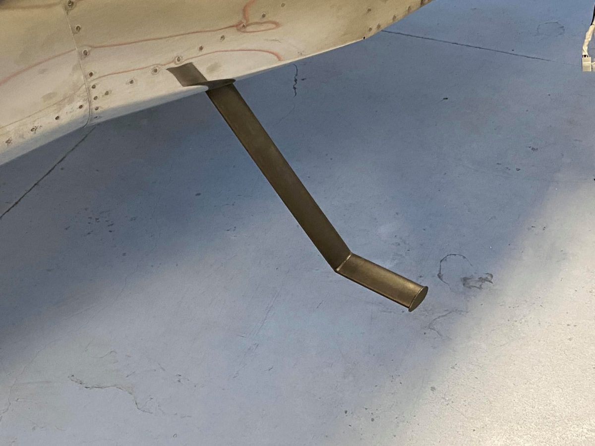
The first of the steps in progress. Each step is secured by two close-tolerance bolts. These are, naturally, an interference fit and are located in a very access-restricted area such that it’s nearly impossible to bring any force to bear on the bolt heat.
I got one in and put the rest in the freezer overnight. Hopefully, the others will surrender today without a fight.
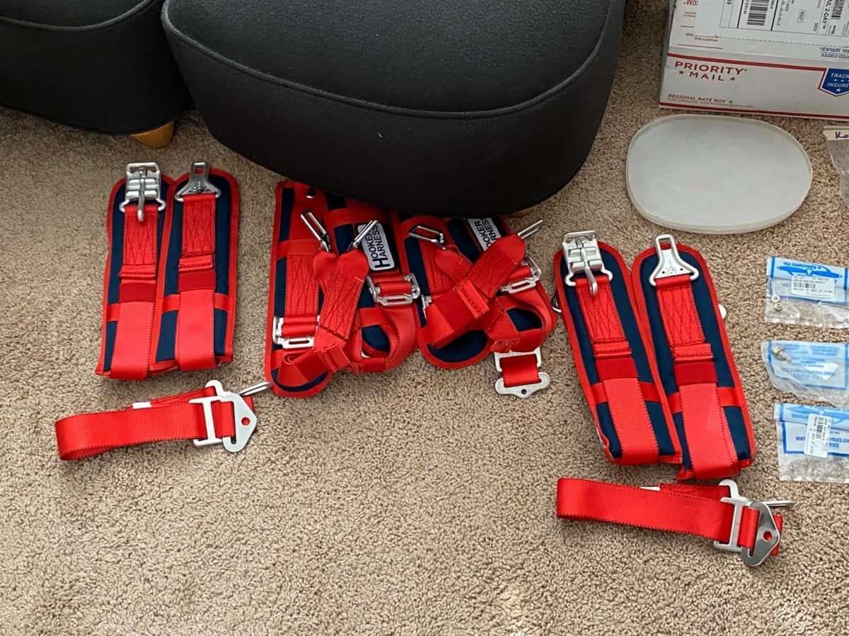
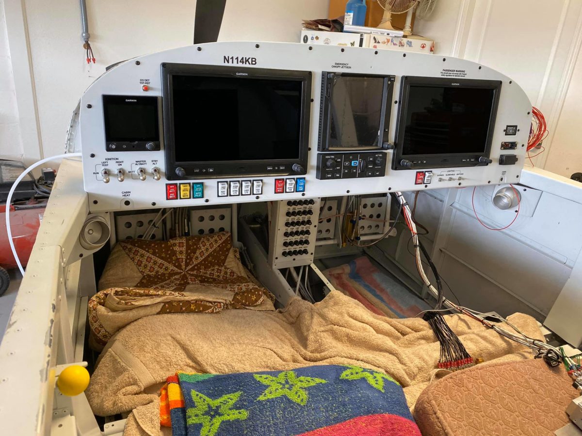
Harnesses laid out for the first time. Not quite ready for installation, but soon…
IBBS installed atop remote Comm 2 radio.
Comm 2/IBBS angle supports seen from below. At the front, the angles are Prosealed to the firewall structure.
Lots of wiring neatening left to do here (obviously), but the Comm 2 radio has now been connected to its harness.
Not much a photo here, but it’s a quick shot of the glareshield cover sitting beneath the canopy. I’ve just affixed the glareshield edging and the Velcro patches for the cover.
The seats have finally been removed from their box! A very nice job done by Abby at Flightline. The carpets can be seen lurking in the background.
I’ve been wondering for over a year (since I built the fuselage forward floor area) about how a flat floor would be achieved with the longitudinal angle in place. Now I see – a very ingenious solution!
If you don’t already know the answer, keep wondering for another few weeks…
Right side wiring cleanup underway. Most of the delay on this side has been due to the lengthy process of deciding upon and executing a solution to the B&C regulator location conundrum.
Problem solved!
Back under the left side for some semi-final wiring cleanup.
The B&C regulator in place. It turned out (completely coincidentally!) that the bolts holding the Comm 2 radio’s forward edge to the support angles were an exact match, width-wise, for the regulator.
Ideally, I’d have used the center hole on each side of the regulator, but there was no way to do that and still fit my hand above it with a wrench. In practice, though, it’s fine; that puppy isn’t going anywhere.
Having finally received the proper 3-blade stripper and crimper for RG400, I set about installing the Comm 2 antenna cable.
Unfortunately, the antenna backplate’s center hole (around the connector) is just a tiny bit too small to allow the terminal to fully seat. I’ll have to remove the antenna tomorrow and open it up with a Unibit.
Oddly, the other side (for the Comm 1 radio) is fine. Weirdly non-standard, right? Van’s – what are ya gonna do? LOL
Pilot’s cabin heat control cable installed. More fun working under the panel – this time, facedown!
My striping idea didn’t work out as well in practice as I’d hoped, so I cleaned off the canopy jettison handle and shot the business end solid red.
As it happens, most of this will have to be stripped off (everything that sits forward of the panel in flight), since the paint is sufficiently thick as to get hung up in the snap bushing. I probably should’ve just left it white. A word to the wise…
Passenger’s cabin heat control cable installed. The prop control cable has also found its home and is fully connected to the governor and appears to be functional. I’ll have to confirm, of course, that I’m getting the expected maximum RPM during the first flight.
Also visible is the installed canopy jettison handle, here in its full aft, dump the canopy, mode. It’s easy to see the streaks made in the red paint by passing through the snap bushing. I’m going to strip most of the paint off and only leave the handle and perhaps half an inch of the shaft red.
The business end of the prop cable attached to the governor. All jam nuts have been tightened and the cotter pin installed. Ready for flight!
Most of the left-side (and all of the central) wires now zip-tied up and out of the way. The Comm2/IBBS tray has been drilled to mount the backup alternator’s external regulator; installation is awaiting the arrival of two K1000-3 nutplates. It seems as though one is always awaiting the delivery of something or other on a project such as this…
Canopy jettison handle has been taped and painted. The idea was a sort of striped effect on the business end, but we’ll see how it turns out.
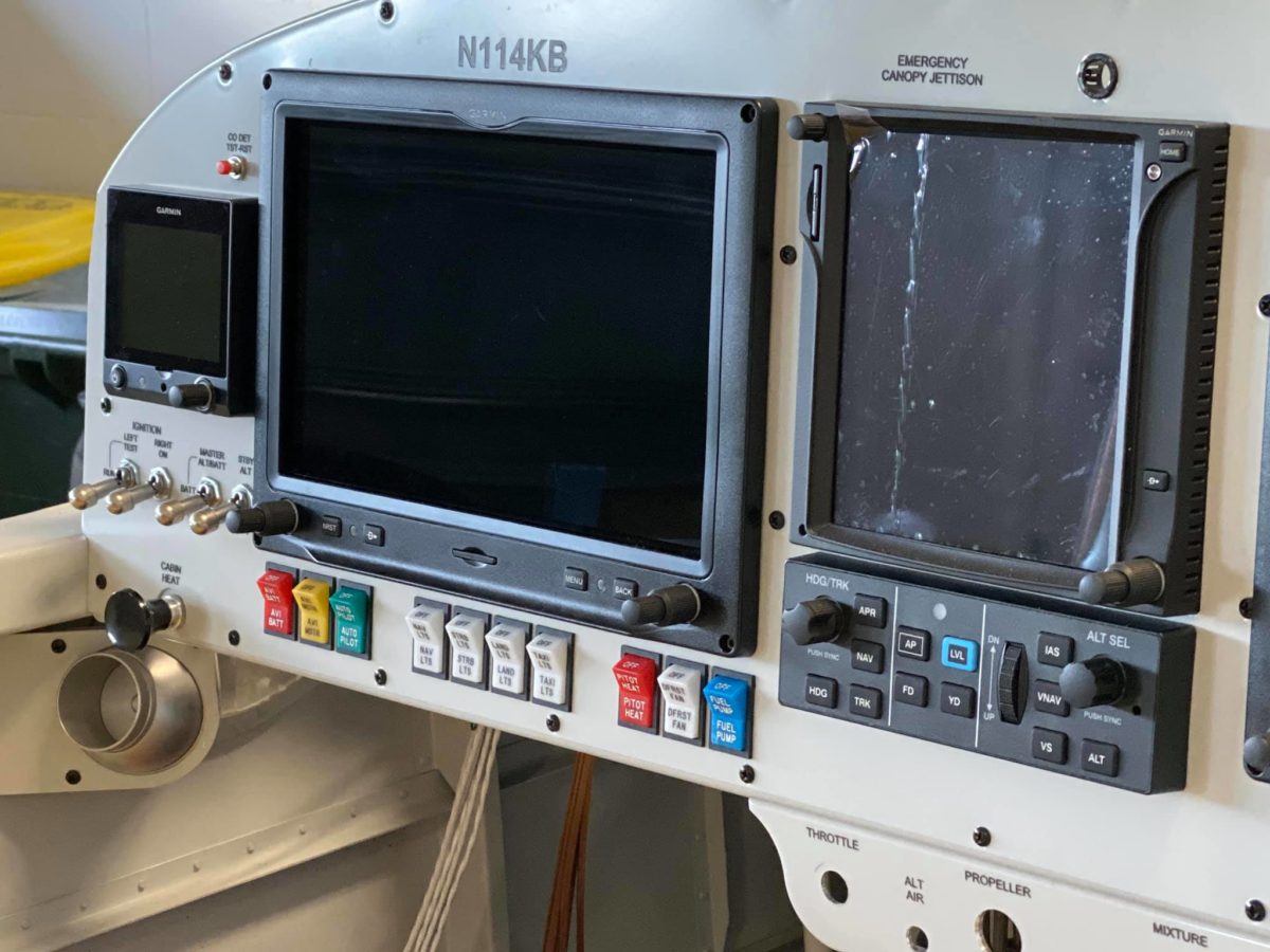
The panel has been drilled for the canopy jettison handle and its supporting snap bushing is now in place. The control cable bracket has been drilled for cables and mounted to the panel. Hope I don’t hit my head on the damn thing while working under the panel for the next few weeks.
BTW, for anyone interested in future, the sizes of the cable holes (for the stock Van’s cables) are, from left to right: ½”, ⅜”, ¾”, and ¾”.
For a guy of my size and limited flexibility, having to work on my back under there with my hands up over my head in a range of awkward angles is pure misery. Mark my words: I will NEVER do this again. Just ask Jeanie…