With Jean’s help this morning, I finally got the yaw damper bridle harness clamps properly adjusted and tightened onto the rudder cables. Thanks, hon!
The corrugated baggage bulkhead cover has gained its ‘Experimental’ decal and been temporarily attached. It’ll come off for the inspection, of course, before being screwed down for keeps.
Passenger-side leather interior panels and armrest installed!
Pilot-side leather interior panels and armrest installed!
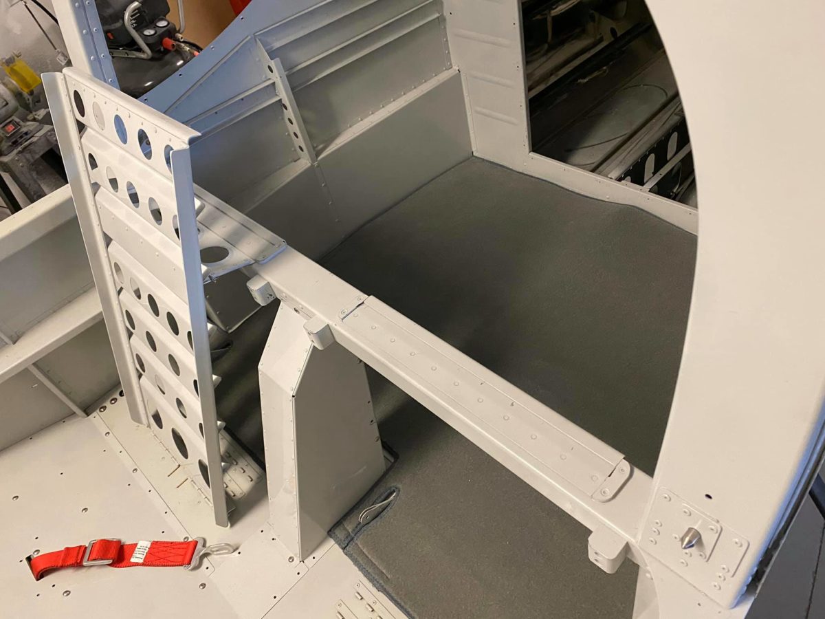
Rear carpet partially installed. I’ve left the pilot-side Velcro temporarily unglued to make it slightly easier to fold the carpet back and remove the baggage floor cover for the upcoming inspection.
Also for ease of pre-inspection assembly, all of the various floor panels have been installed with only a subset of their total screw complement.
Footwell carpets have been partially installed. The floppy bits at the aft ends will be Velcroed in place once the control column covers have been fully screwed down following inspection.
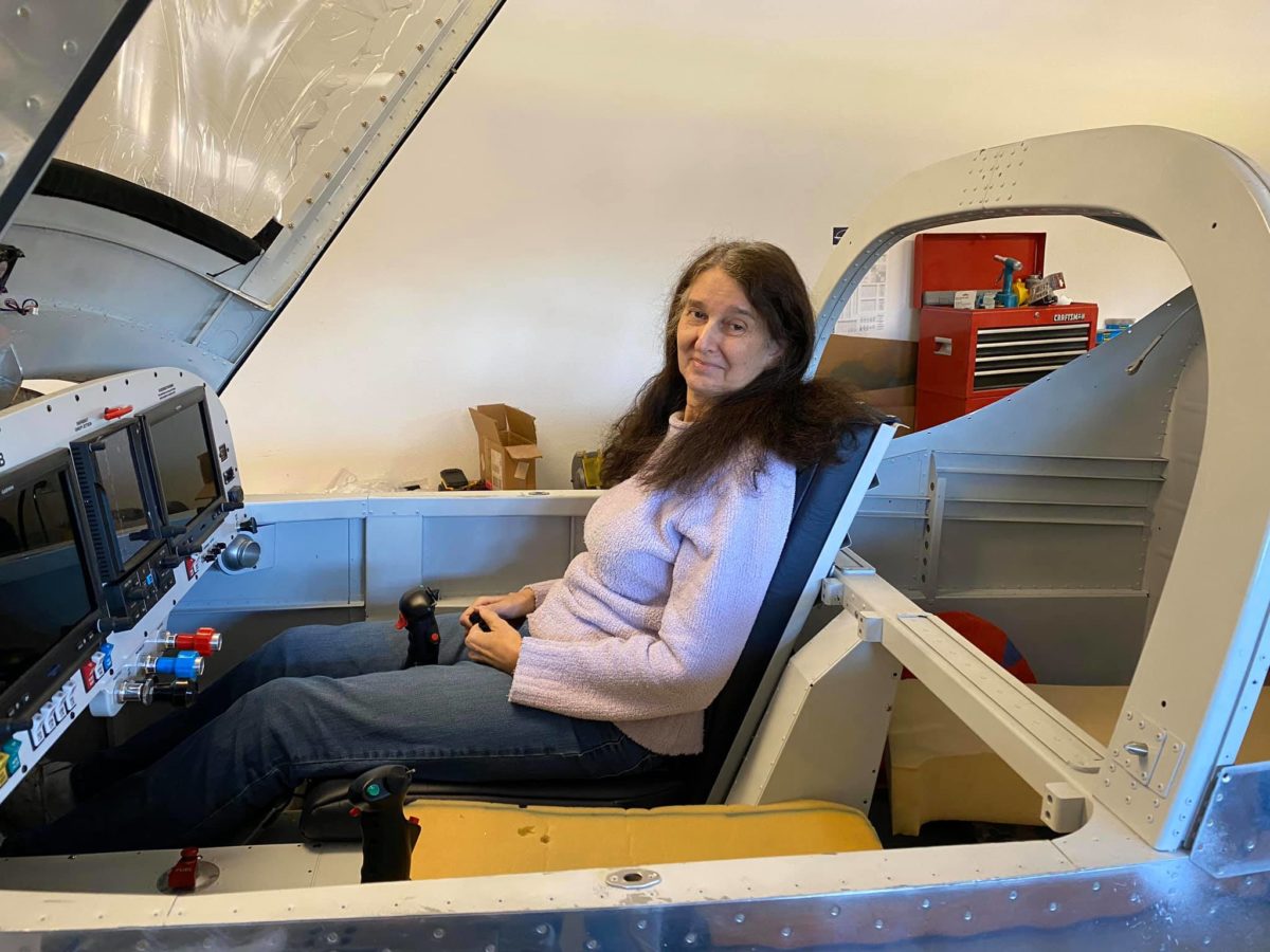
Passenger seatback and cushions temporarily in place. They’ll be coming out shortly to facilitate seat belt installation, but I needed them in there for tomorrow’s first task…
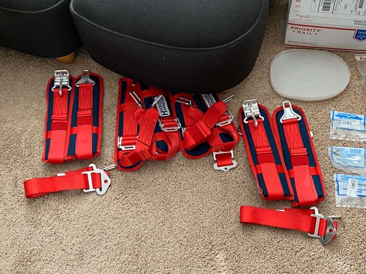
Harnesses laid out for the first time. Not quite ready for installation, but soon…
IBBS installed atop remote Comm 2 radio.
Comm 2/IBBS angle supports seen from below. At the front, the angles are Prosealed to the firewall structure.
Lots of wiring neatening left to do here (obviously), but the Comm 2 radio has now been connected to its harness.
Not much a photo here, but it’s a quick shot of the glareshield cover sitting beneath the canopy. I’ve just affixed the glareshield edging and the Velcro patches for the cover.
The seats have finally been removed from their box! A very nice job done by Abby at Flightline. The carpets can be seen lurking in the background.
I’ve been wondering for over a year (since I built the fuselage forward floor area) about how a flat floor would be achieved with the longitudinal angle in place. Now I see – a very ingenious solution!
If you don’t already know the answer, keep wondering for another few weeks…
Right side wiring cleanup underway. Most of the delay on this side has been due to the lengthy process of deciding upon and executing a solution to the B&C regulator location conundrum.
Problem solved!
Back under the left side for some semi-final wiring cleanup.
The B&C regulator in place. It turned out (completely coincidentally!) that the bolts holding the Comm 2 radio’s forward edge to the support angles were an exact match, width-wise, for the regulator.
Ideally, I’d have used the center hole on each side of the regulator, but there was no way to do that and still fit my hand above it with a wrench. In practice, though, it’s fine; that puppy isn’t going anywhere.
Having finally received the proper 3-blade stripper and crimper for RG400, I set about installing the Comm 2 antenna cable.
Unfortunately, the antenna backplate’s center hole (around the connector) is just a tiny bit too small to allow the terminal to fully seat. I’ll have to remove the antenna tomorrow and open it up with a Unibit.
Oddly, the other side (for the Comm 1 radio) is fine. Weirdly non-standard, right? Van’s – what are ya gonna do? LOL