Firewall forward, canopy continued…

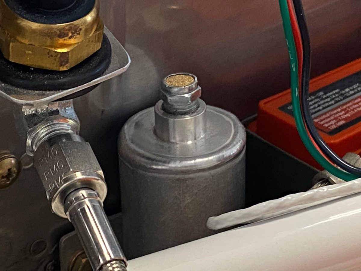
When I removed the plug from Van’s supplied brake reservoir, it was galled and stripped. It had been threaded in way too tight and without lubricant. Never a good thing.

I ordered a stainless replacement, applied a little Fuel Lube (actually EZ Turn, these days), and it went right in.

Since the brakes have already been bled, I REALLY didn’t want to remove the reservoir or tap it in place. Happily, neither was necessary.

Canopy guide pins receiving a little paint.

Pilot-side canopy guide pin riveted in place.

Modeling clay (way too much, as it turned out) applied per the instructions.

Also too much modeling clay…

One of the canopy guide plates riveted in place.

And the other one…

Panel component installation continued…

Pilot’s cabin heat control cable installed. More fun working under the panel – this time, facedown!

My striping idea didn’t work out as well in practice as I’d hoped, so I cleaned off the canopy jettison handle and shot the business end solid red.

As it happens, most of this will have to be stripped off (everything that sits forward of the panel in flight), since the paint is sufficiently thick as to get hung up in the snap bushing. I probably should’ve just left it white. A word to the wise…

Passenger’s cabin heat control cable installed. The prop control cable has also found its home and is fully connected to the governor and appears to be functional. I’ll have to confirm, of course, that I’m getting the expected maximum RPM during the first flight.

Also visible is the installed canopy jettison handle, here in its full aft, dump the canopy, mode. It’s easy to see the streaks made in the red paint by passing through the snap bushing. I’m going to strip most of the paint off and only leave the handle and perhaps half an inch of the shaft red.

The business end of the prop cable attached to the governor. All jam nuts have been tightened and the cotter pin installed. Ready for flight!

Panel in process

Most of the left-side (and all of the central) wires now zip-tied up and out of the way. The Comm2/IBBS tray has been drilled to mount the backup alternator’s external regulator; installation is awaiting the arrival of two K1000-3 nutplates. It seems as though one is always awaiting the delivery of something or other on a project such as this…

Canopy jettison handle has been taped and painted. The idea was a sort of striped effect on the business end, but we’ll see how it turns out.

The panel has been drilled for the canopy jettison handle and its supporting snap bushing is now in place. The control cable bracket has been drilled for cables and mounted to the panel. Hope I don’t hit my head on the damn thing while working under the panel for the next few weeks.

BTW, for anyone interested in future, the sizes of the cable holes (for the stock Van’s cables) are, from left to right: ½”, ⅜”, ¾”, and ¾”.

For a guy of my size and limited flexibility, having to work on my back under there with my hands up over my head in a range of awkward angles is pure misery. Mark my words: I will NEVER do this again. Just ask Jeanie…

Empennage, rudder, horizontal stabilizer, vertical stabilizer continued…

Rudder bottom fairing and taillight complete.

Spinner backing plates ready for installation.

Spinner screw holes drilled up to #19.

Empennage tip fairings and spinner gap fillers ready for installation.

The tip fairings are definitely not perfect, but they’re perfectly airworthy, so I’m fine with moving forward at this point. So far as I’m concerned, getting them perfect falls under paint shop surface prep – and they’ll be paid plenty for the work.

Left horizontal stabilizer tip fairing riveted in place.

Right horizontal stabilizer tip fairing riveted in place.

Vertical stabilizer tip fairing riveted in place.

Spinner plate assembly and front bulkhead drilled for nutplates and countersunk.