Panel component installation progress

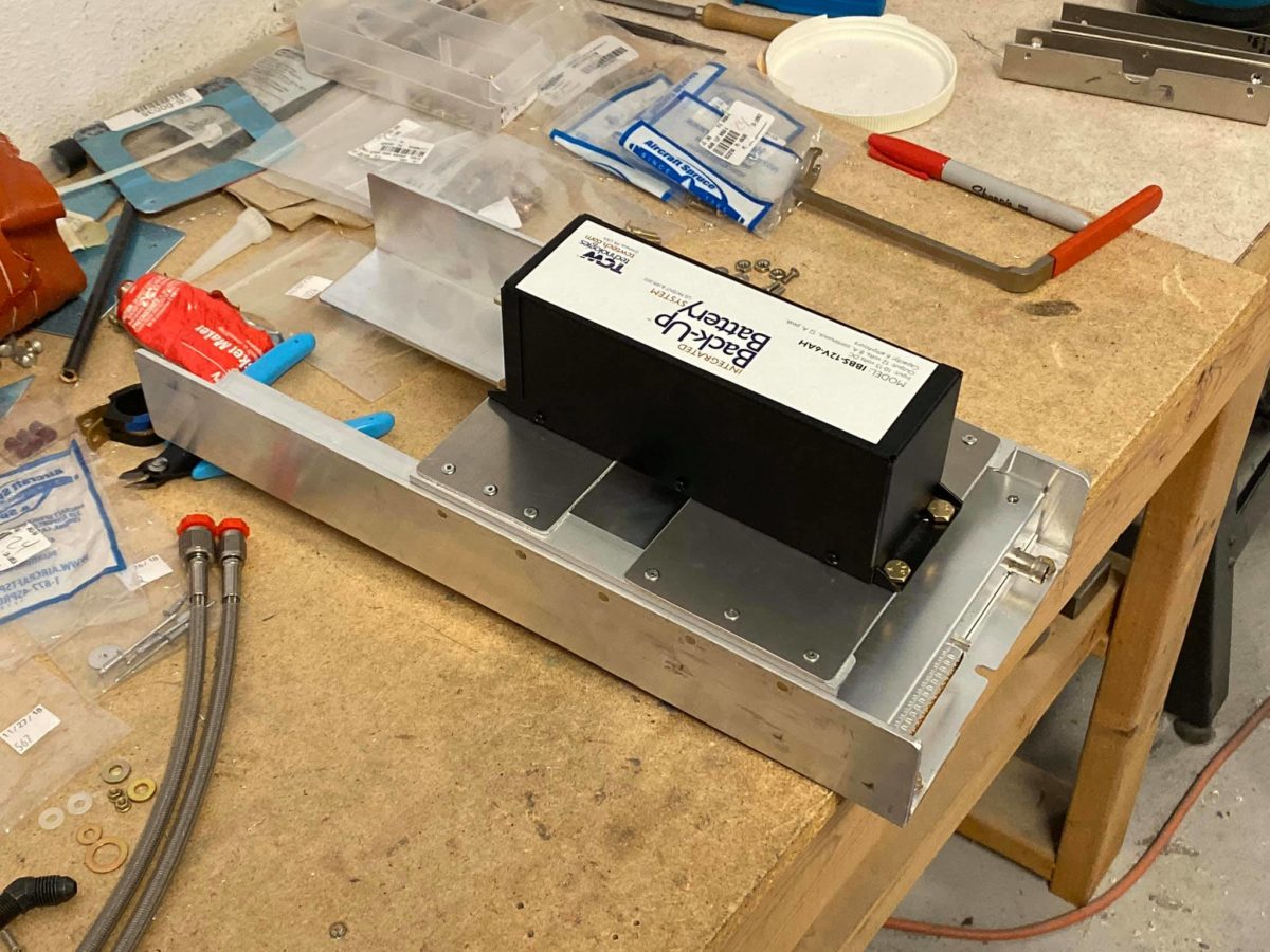
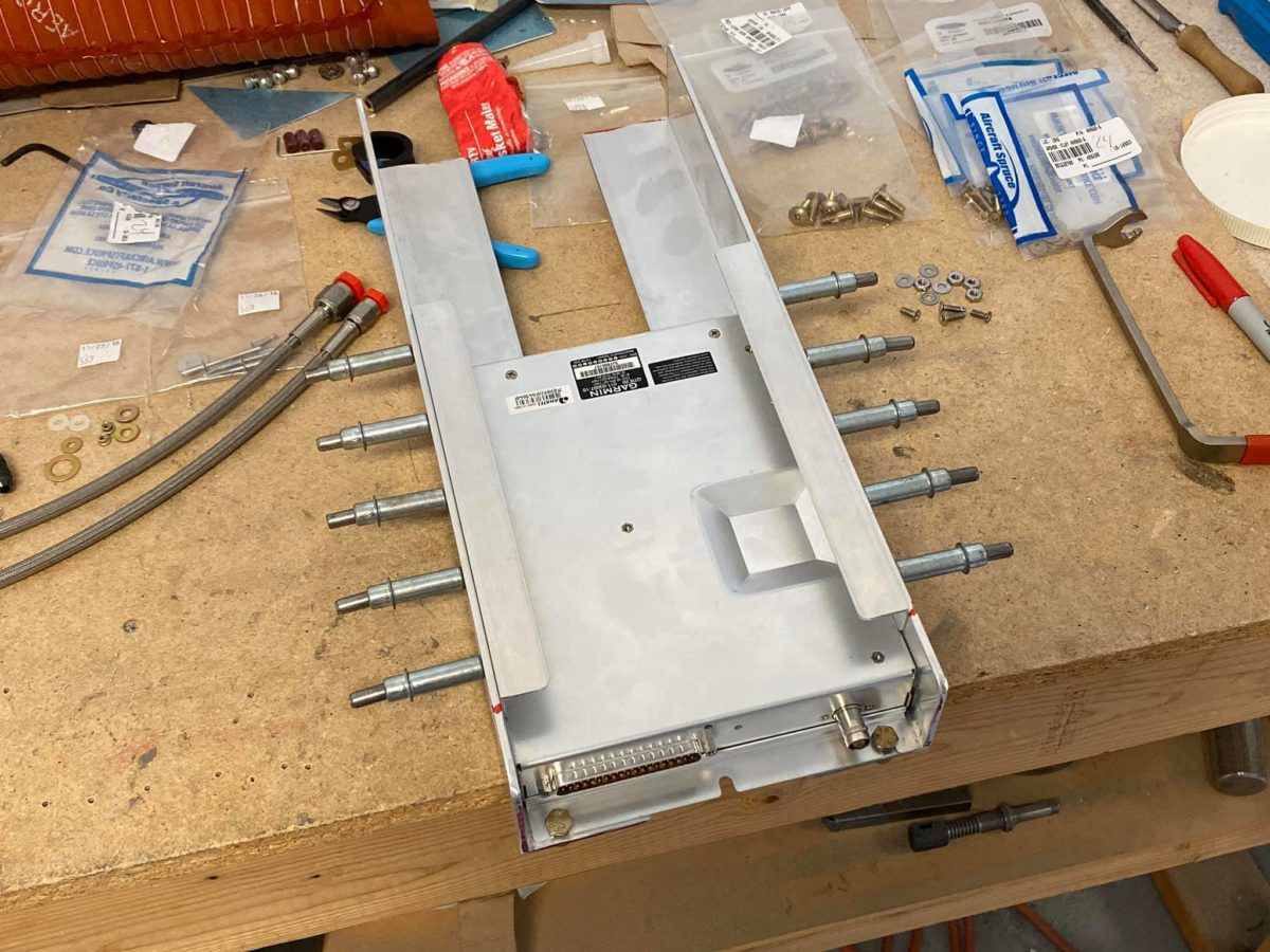
Transponder mounting plate in progress.

Transponder tray attached to the mounting plate.

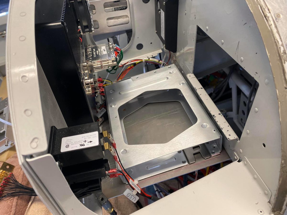
Transponder tray and mounting plate clamped in place for drilling.

Transponder and backplate attached to the mounting tray and clecoed in place.

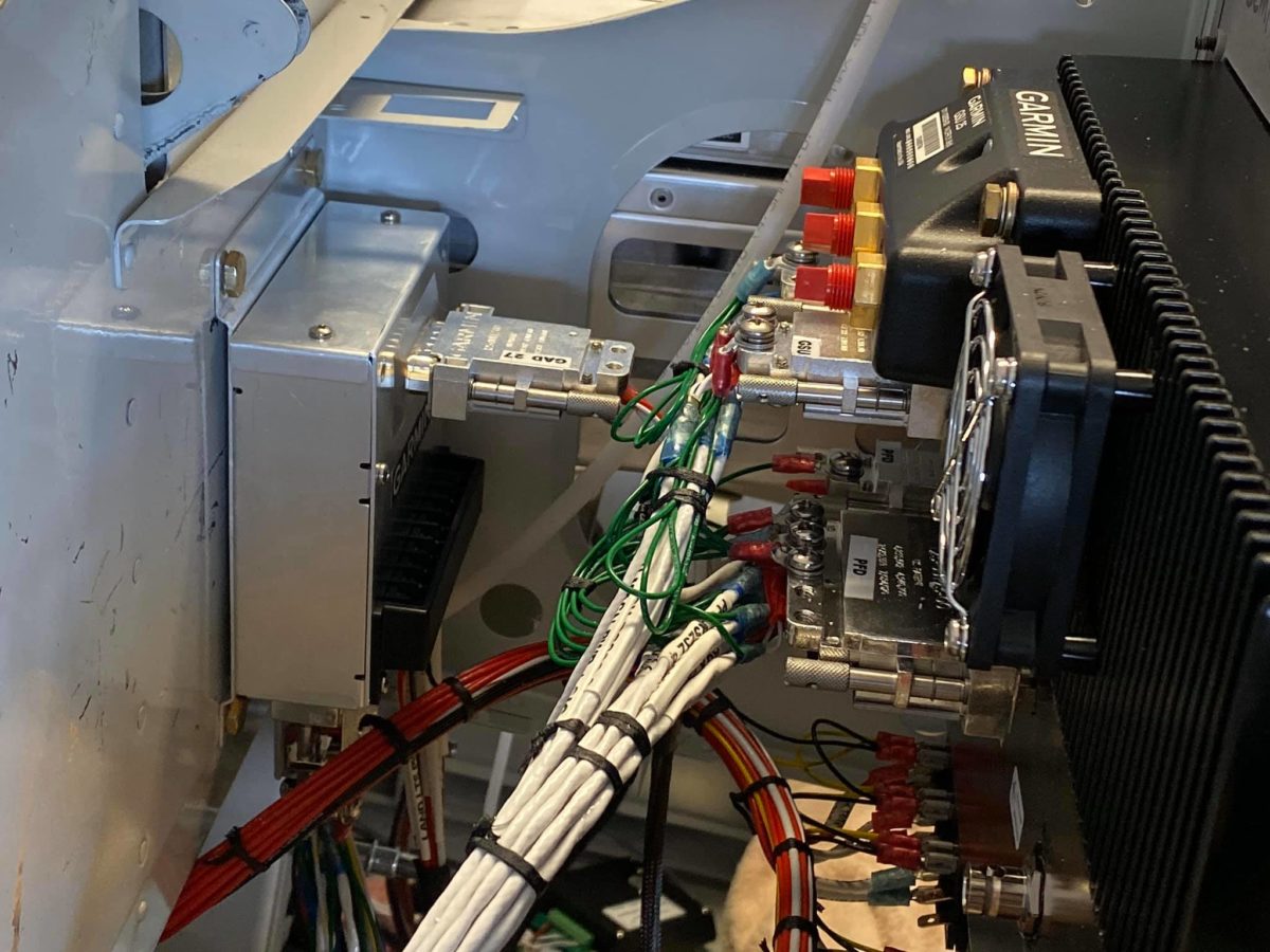
Left-side wiring has now been largely cleaned up. The white wire bundle still dangling to the left is Stein’s main buss – I’ll attach it to the forward face of the sub-panel next week once I receive the ANL fuses, etc. required for my dual-alternator configuration. The output wire from the shunt will run to the buss bar’s open post and it’ll just be easier to attach before installing it up on the sub-panel.

The white wire trailing to the right is the OAT probe which will have to be brought down behind the breaker panel and through the central tunnel until exiting the left side of the airplane with the main harness and making its way to the first inspection panel in the left wing. I hope the probe wiring is long enough…

Next up will be pulling the breaker panel, trimming the edges of the support bracket to clear the breaker buss bar hardware on the backside of the panel, and applying some adhesive rubber insulation to the inside of the bracket. Once that’s done, the breaker panel will be reinstalled and the Left & Right main harnesses will be zip-tied up out of the way along with the long breaker pigtail.

Then, onto the right side dangling bits. I’m leaving next Friday for the F1 race in Austin, so Thursday is my deadline to get all of this done. We’ll see how I do… 

Panel progress

Garmin box mounting underway. Yes, it’s a titanic pain in the ass, both to locate them so that each piece of the puzzle fits, and to actually reach both sides of each fastener for installation. Nevermind the two or three times most of them had to come off and go back on.

Anyway, here’s the GAD27 in and ready to fly.

The GAD29 and GEA24 have now both found their homes. Wiring cleanup and zip-tying are obviously yet to be done…

This area of the sub-panel will also mount the main buss bar, though probably from the forward side so its dangling wires don’t impinge on the magic boxes.

Here we have the transponder, its tray, and the mounting plate I’m fabricating for them. I thought about using hinges, but don’t think I’ll bother; I’m just going to drill the forward and aft edges into (respectively) the panel and sub-panel lower flanges, install nutplates, and screw it on there.

Finding a lateral location and orientation for the transponder where it isn’t hard up against the switch wiring in that area has been a major challenge. The answer is going to be mounting it with the backplate inboard. If it ever needs to come out, I’ll have to drop the whole plate, but that’s not a concern.

Here’s the remote Comm 2 box mounted on its angles. I still have to figure a way to attach the front ends to the firewall angle on which they’re resting and the aft ends to the sub-panel. I’ll probably use two short lengths of angle for the latter; the former is still a mystery.  

This area of the sub-panel will also mount both the CO detector and the ground block.