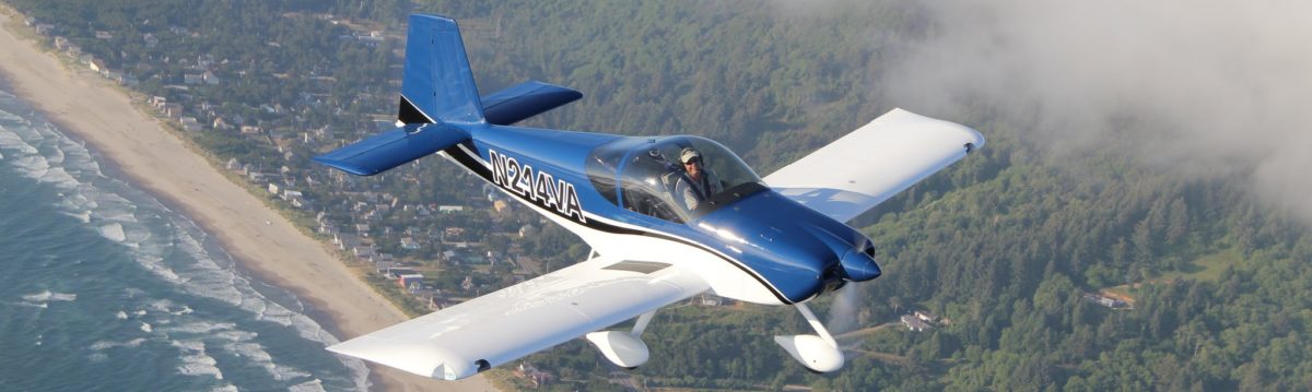
Thanks for the visit, Turner! It was great to finally meet you in person and to spend some time poring over your beautiful airplane.

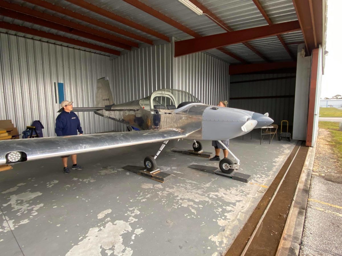
Weight and balance underway!

Weight and balance underway! On the scales…

Weight and balance underway!
Great job by On-Site Weight & Balance; thanks, Sal!

First fueling about to commence…

And…a couple of fuel leaks found, one minor, one somewhat less so. Argh. — with Alex Cole.

The detanking underway…

The detanking underway…

Meanwhile, I received a gorgeous pair of landing/taxi light lenses from Big Sky Robotics. Very nicely made and highly recommended.

The new lenses with their nutplate strips setting up.

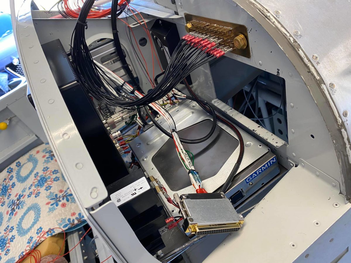
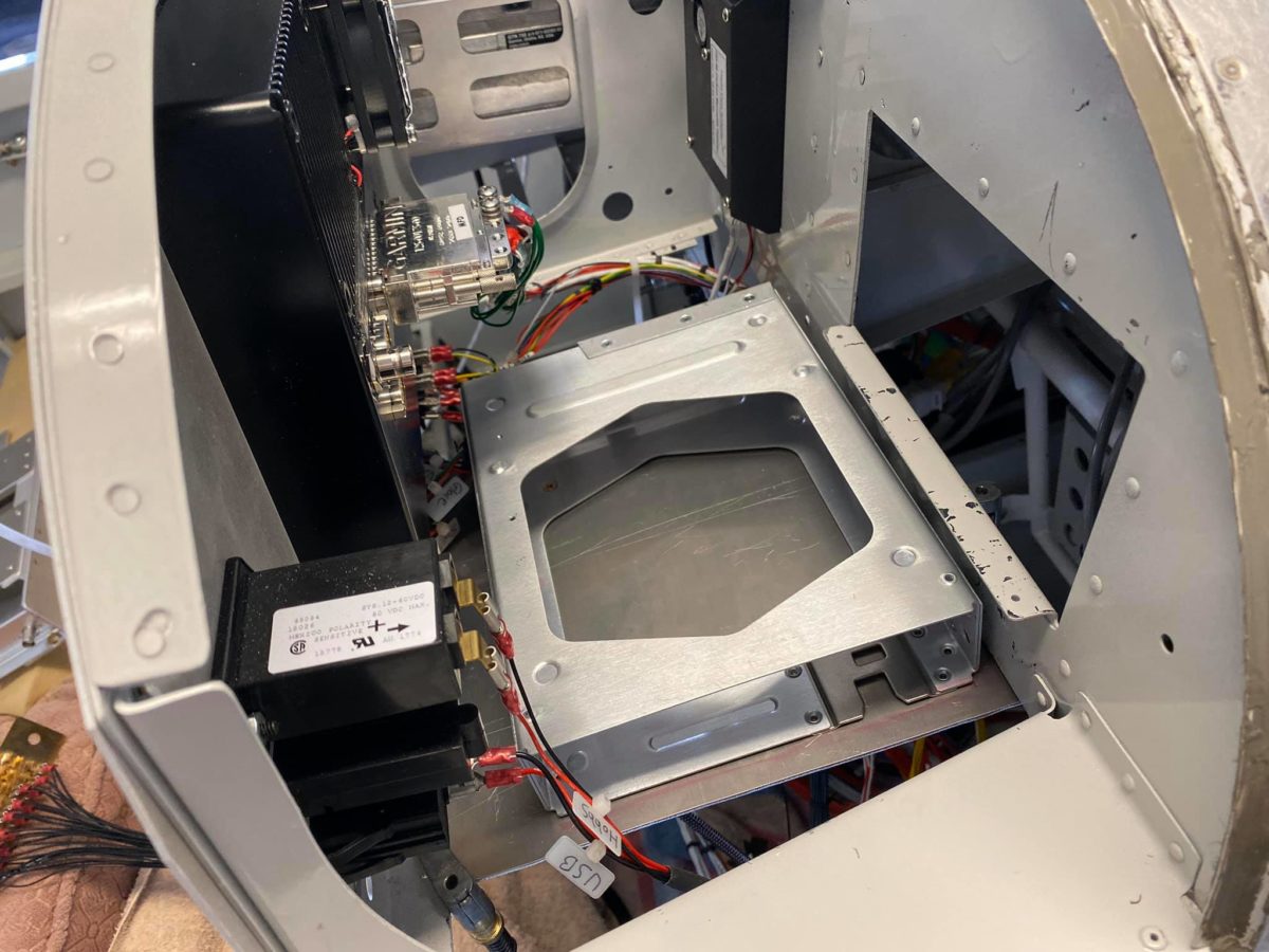
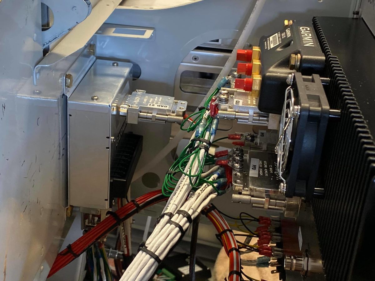
IFR pitot-static and transponder certifications underway.

IFR pitot-static and transponder certifications underway.

IFR pitot-static and transponder certifications underway.
Great work from Volusia Aviation; thanks, Sean!

New lens installed.

New lens installed.