With Jean’s help this morning, I finally got the yaw damper bridle harness clamps properly adjusted and tightened onto the rudder cables. Thanks, hon!
The corrugated baggage bulkhead cover has gained its ‘Experimental’ decal and been temporarily attached. It’ll come off for the inspection, of course, before being screwed down for keeps.
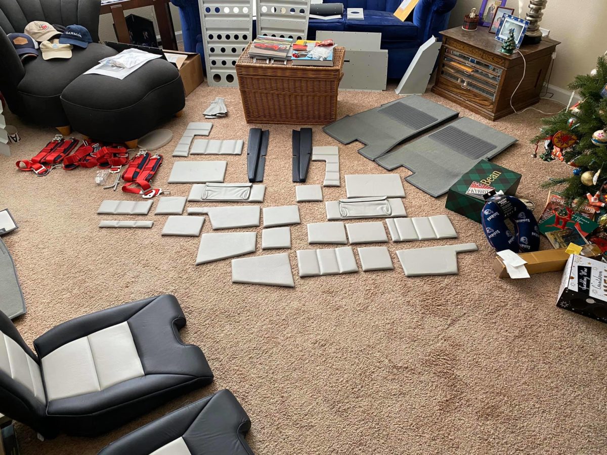
Passenger-side leather interior panels and armrest installed!
Pilot-side leather interior panels and armrest installed!
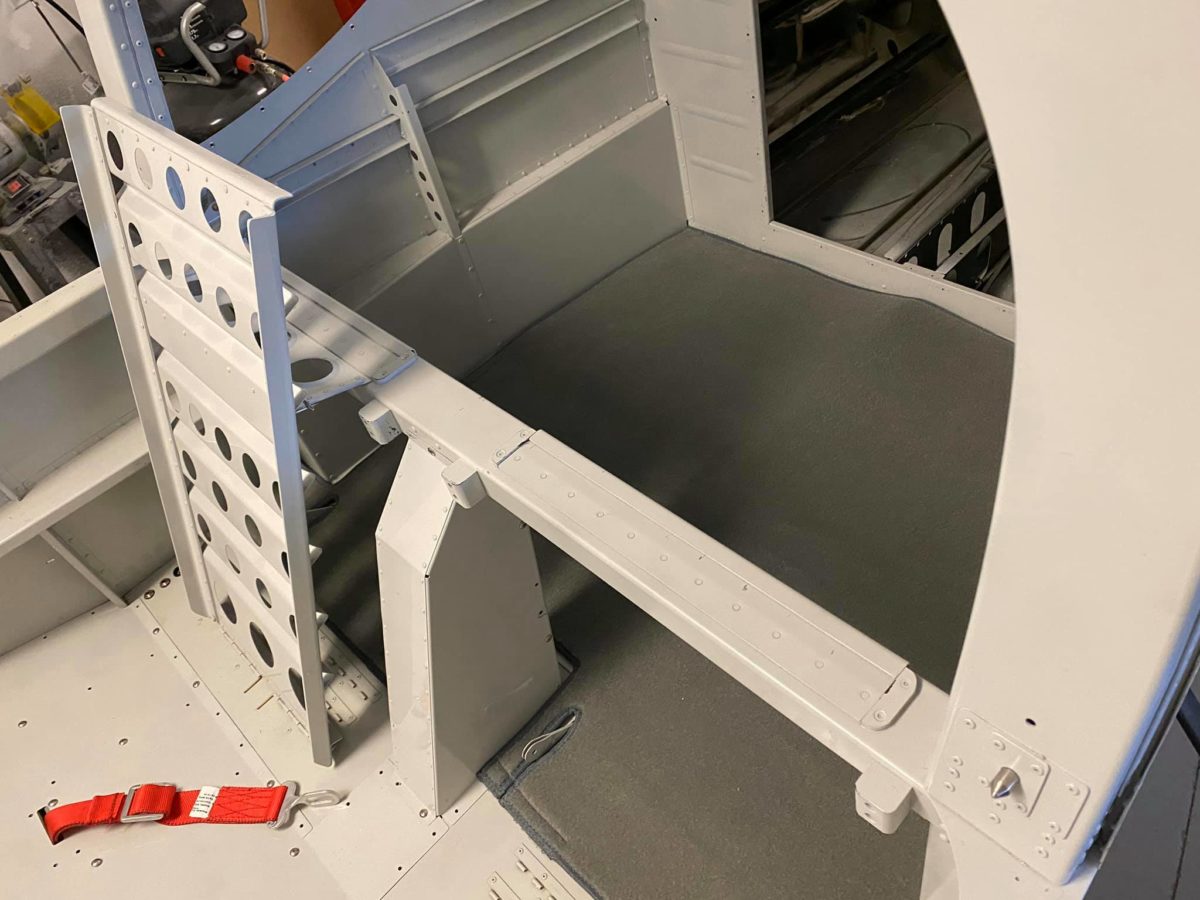
Rear carpet partially installed. I’ve left the pilot-side Velcro temporarily unglued to make it slightly easier to fold the carpet back and remove the baggage floor cover for the upcoming inspection.
Also for ease of pre-inspection assembly, all of the various floor panels have been installed with only a subset of their total screw complement.
Footwell carpets have been partially installed. The floppy bits at the aft ends will be Velcroed in place once the control column covers have been fully screwed down following inspection.
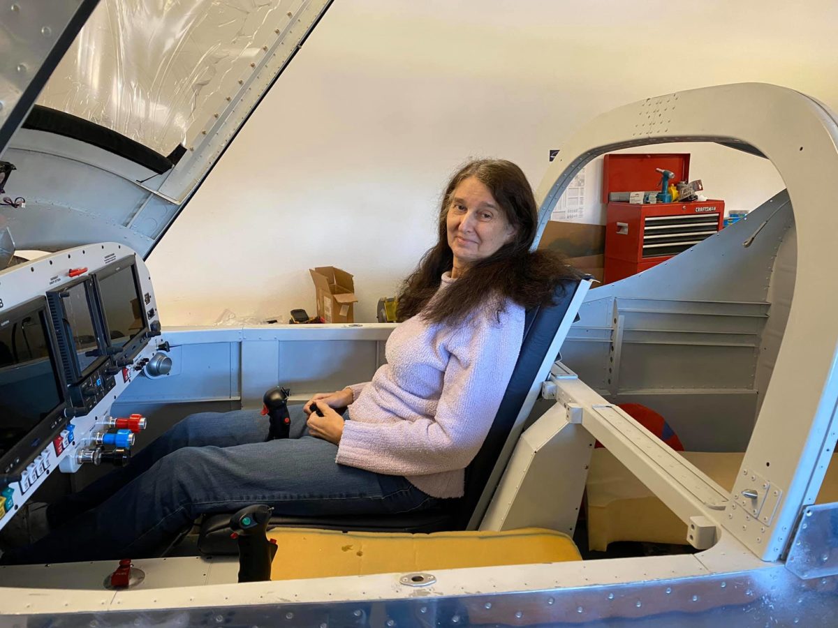
Passenger seatback and cushions temporarily in place. They’ll be coming out shortly to facilitate seat belt installation, but I needed them in there for tomorrow’s first task…
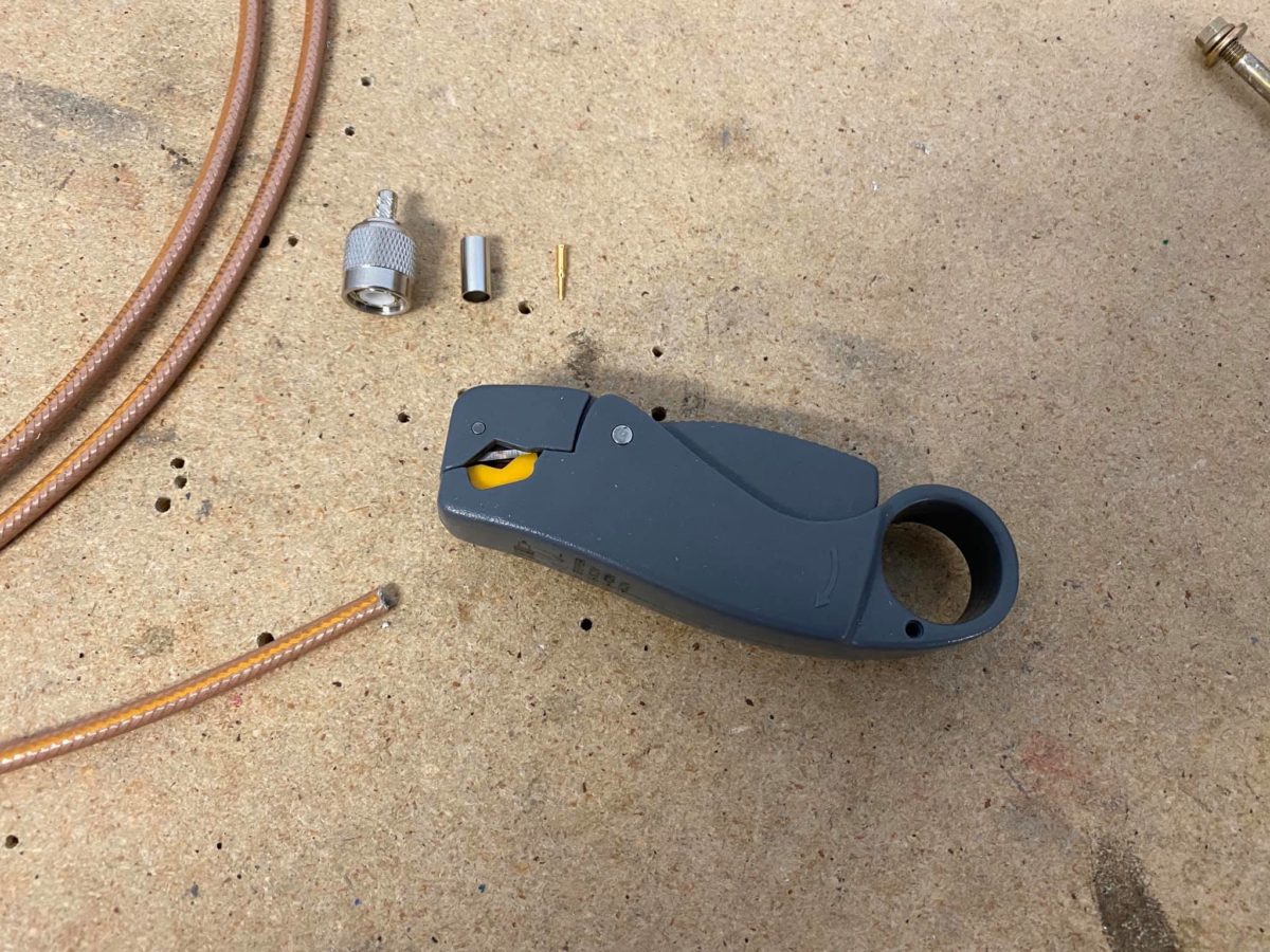
Preparing to install a TNC connector (for WAAS GPS) to a length of RG400 cable. This 3-bladed stripper does most of the necessary stripping in a single step.
Here we see that all three cuts have been made simultaneously.
Each piece of outer casing (along with the underlying shielding layers, as appropriate) is removed with the gentle use of pliers.
The pin is slid into place and the amount of necessary center conductor trimming is readily apparent.
I used a razor knife to trim an additional 1/16″ from the outer casing.
The center conductor is trimmed and the pin is then slid back on in preparation for crimping.
I like to leave it just shy of the insulator as shown here. If the pin is bottomed on the insulator, you can’t be sure that the wire is fully inserted in the pin. This is a closeup of a very small assembly – the gap is probably on the order of 1/32″.
Pin crimped! Don’t forget to do a pull test…
Slide the barrel onto the cable (don’t forget!) and push the connector on until the pin clicks (it’s very obvious) into place. The neck of the connector should easily slip under the braided shield.
At this point, I like to do an initial test with a meter to confirm that the center pin isn’t grounded to the connector.
Slide the barrel up to the connector and crimp.
Don’t forget to do a final test with a meter to confirm that the center pin isn’t grounded to the connector.
If it tests good, then it’s all done and ready to install.
I should point out that BNC connectors are done with the same tools in exactly the same fashion.
I connected one end to my GTN 750 and ran the other end forward through the firewall. Once I’ve fabricated the antenna mount, I’ll final-route the cable, install a TNC connector on the end, and attach it to the antenna.
Pilot-side Infinity stick grip wires have been routed and identified with a meter.
The pilot’s Infinity grip has been installed; very exciting!!
Those two look good in there! It feels as though it’s getting close now…